Before we begin, I am going to mention a few terms to keep in mind and briefly explain what they mean (in my words).
- Continuity – metal physically connected to metal resulting in a closed circuit, whether that be wires, contacts etc.
- “Dry” – meaning no electricity is imposed by something like a relay contact
- Contacts – in regards to a relay, the portion of the relay that switches state to either open or close a circuit
- Dry Trip or Dry Trigger – usually meaning that the dry contacts of a relay are used as a means to provide a trigger to a device such as a gate operator or door operator
- Normally Open (NO) – open circuit / contacts, no continuity
- Normally Closed (NC) – closed circuit / contacts, continuity
- Common terminal – movable part of a relay, like a pendulum, that throws electricity from one terminal to another.
- Electrified crash bar or panic bar – the long metal retractable bar that you may see spanning the width of some doors. Used to retract the latch in order to open the door.
- Electromagnetic lock or Mag Lock – A strong electro magnet that secures to an armature plate on the door in order to keep a door locked and secured.
- Electric Strike – mechanical / electrified latch that lives on or in the door frame. When powered it usually releases /unlocks.
- Fail-safe – for a mag lock or electric strike…releases when there is no power applied.
- Fail-secure – for an electric strike…remains locked when no power is applied.
- REX – request to exit. Could be a motion sensor, push button etc.
- Wave Sensor – no touch device mounted on a wall, similar to a push button that can do things such as break power to a lock, or dry trip an auto operator.
To understand relays, it is first helpful to understand the general idea of how electricity flows. I will be referring to DC current in this post because that is the power source that I work with on a day to day basis. The general principle also applies to AC however. With DC, we say positive and negative. With AC we say hot and neutral.
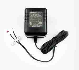
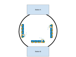
Electricity flows from a power source, through a device and then back to the source. Think of it like a train leaving station A, going through station B and then returning back to station A on the other side of a circular track. Take for example a simple DC transformer that you would plug into the wall. It has two leads, one positive and one negative. Electricity flows from the positive side (or leg), through the device it is powering, and then back to the source on the negative leg.
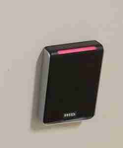
Let’s now talk about something like an electromagnetic lock that is used to keep a door locked. The lock is usually powered by 12 or 24 Volts DC (VDC). The door remains locked until someone swipes their badge at a card reader to gain access through the door (or in the event of a fire alarm, a mag lock must drop power to allow free egress through the door). Sometimes a door may have an auto operator, electrified crash bars, mag locks, wave sensors, REX’s, card readers etc. This is a prime example of where relays would come into play.
Sometimes the electricians may install the crash bar power supply above the door, the auto operator company controls the auto operator, and the access control company may control lock power. A way to integrate all of these devices so that they can work in conjunction with each other would be by utilizing multiple relays.

Simply put, relays can switch the positive leg of a circuit on or off – similar to a light switch. Many times, the contacts of a relay are referred to as “dry”. This means that the relay is not providing any power itself, but only switching the positive leg of a circuit coming from somewhere else. The way that a relay switches its contacts is by being turned on or off. It is also common to use a relay to provide a dry contact closure for another device such as an automatic door operator. In this case, there is no voltage or current that comes into play through the relay contacts. It would be as if you were standing in front of an automatic operator and using a small jumper wire to connect or “short” two terminals together to initiate a trigger (see video below).
Let us refer to an Altronix RB610 relay. The relay itself is powered via 12 or 24VDC. When the relay is ON, the contacts are in a certain state. When the relay is OFF, the contacts are in another state. These states are referred to as Normally Open (NO), Normally Closed (NC) and there is common terminal (C). Think of the common terminal as a pendulum that swings back and forth to either make or break the circuit. When an RB610 relay is powered OFF, this is considered the “normal” state of the relay. So for example, when the RB610 has no power, the contacts are as they read, between the C terminal and NC terminals there is continuity, or a closed circuit. Between the C terminal and NO terminals there is an open circuit, or no continuity.
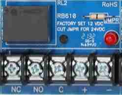
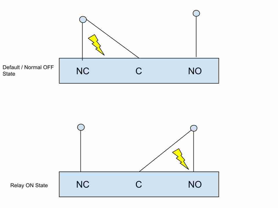
When the relay receives power, the states reverse. NO becomes closed and NC becomes open. An RB610 is referred to as a single pole, double throw (SPDT) relay. This means that you have (1) common terminal for one power source, while a DPDT relay would have (2) common terminals for two different power sources. The “double throw” (DT) portion of the term, means that you can have two different states from one relay simultaneously, or you can power one device while un-powering another device at the same time upon triggering the relay. Think of a standard light switch as being single pole, single throw because you can only have one device, say a light, on or off. You cannot power one light and un-power another light at the same time.
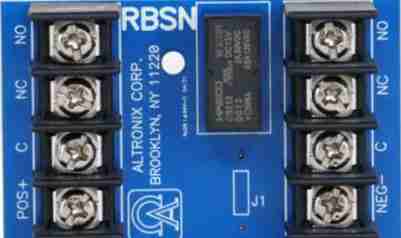
Altronix RBSN Double Pole Double Throw (DPDT) relay.
Relays are incredibly versatile devices. I will go over a few use cases.
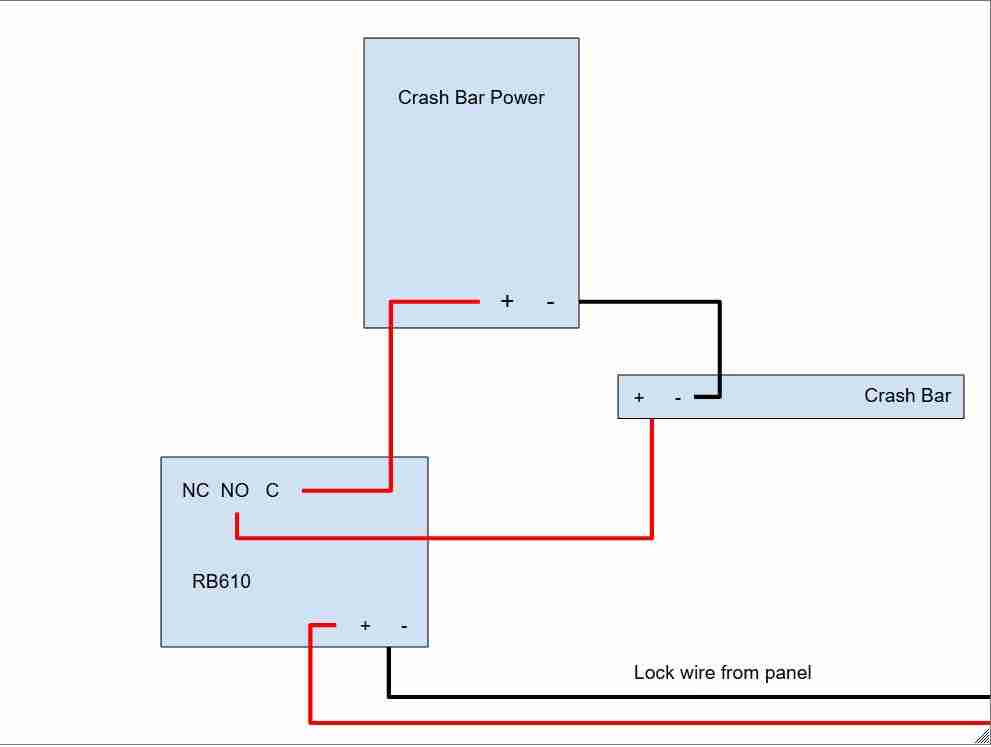
Let us say that you have a door with an electrified crash bar or panic bar. The power supply for this bar is located above the door and is totally separate from your security equipment enclosure that contains all of your control boards. A viable approach to triggering the electrified crash bar with an RB610 relay would be to connect your usual lock wire that comes from your panel to an RB610 positive and negative. Set lock power to NO as if using it for an electrified strike. The RB610 will be OFF until a badge is read. Once a badge is read, from your panel, power will be sent to the RB610. You would connect your common or hot from the crash bar power supply to your C on the RB610, and then connect your outgoing wire to the crash bar to the NO terminal of the relay. While sitting idle, the crash bar will not have power as the relay is OFF and there is no continuity from the power supply to the crash bar through the relay contacts. As soon as the relay changes state due to receiving power, the NO contact will have a close on it resulting in current flow from C to NO.
Another simpler but equally as useful scenario would be a door with an auto operator and a card reader to gain access through the door. Auto operators generally only need a dry trigger in order to activate. With an RB610 relay, you can connect your lock wire positive and negative to the relay. Set your lock power for NO from your panel. The relay will be off unless a badge is read. Connect a piece of 2-wire to C and NO on the relay and then connect to the auto operator dry trip. Once a badge is read, the relay will change state, thus dry triggering the auto operator.
Think of relays as switches that are triggered by some kind of event…a card read, a button press, motion etc. When the relay is turned on or off, the contacts change state which in turn powers or un-powers a device.